Fake caustics in Blender

Caustics are those interesting highlights caused by light refracting through glass, water or optically similar media. Creating caustics in CGI is not only tricky and time consuming, it also takes a considerable amount of computing power and time to render. Being able to fake this is a useful technique.

I came across a great technique in this video by Polyfjord and simply had to have a go.

Alright lads, how about some swords then?

Amongst the variegated duties that befall me, making gifts for the ankle biters whom I adore and love so dearly is one that is particularly relevant when Pesach rolls around and Afikoman ideas are few and far between. This year I decided to make the youngest of my clan, both of them being decidedly male, a personalised sword each. Since they are at the stage where swords of any description are just fine, thank you very much, I did not spend too much time on the finishing.

The swords were printed in 12 parts each and assembled using aluminium dowels and epoxy glue. After some minor sanding (the boys are not all that fussy so here quantity is king, not quality) I applied a few base coats of white acrylic, then oversprayed metallic silver acrylic. The gold metallic highlights were airbrushed in afterwards, as were the handle colours. The last thing applied was a few coats of varnish.

Their reaction? Their collective jaws dropped, then they immediately started fighting with them. Fortunately after warning them that the paint is easily damaged they ceased all violence forthwith.

Sword wireframe

AWS for WiFi lighting

What with COVID-19 basically shuttering my business for the moment, my excuses for Not Getting On With Stuff were wearing a little thing. So, I schlepped out the ATX PSU I had secured a while back during a wild spree of sale-ing and employed my super-secret-sauce to rig it up to the LED strips that adorn my dining-room arch – AWS. Which stands for Advanced Wiring System.

This wiring system/method has taken me decades to develop, and I’m sure the results speak for themselves. Yup, that’s prime-quality no-name-brand gaffer tape there, me hearties.

Also, a couple of small PCBs I rustled up in the light of a full blood moon, some of which contains the firmware I wrote (in an ESP32 – absolutely love that chip) in order to make the nefarious devices cycle the colours of the LEDs and interface with my WiFi so I can fiddle with this from the comfort of anywhere except for the dining room, should I desire to do so.

Since I did not have a mounting cage for the ATX PSU, I designed and 3D printed one, likewise for the case holding the PCBs which is also 3D printed.

Custom ATX PSU bracket for wall mounting.
3D printed project box I designed for this sort of thing.
The ensemble with your actual Gaffer tape.

3D printable stretchy face shield

NOTE: This has not been medically tested yet (if you can help with that, please contact me). Use this at your own risk.

What with Coronavirus/COVID-19 running wild, all sorts of PPE are running in short supply, so we need some innovation to come up with alternatives. This face shield design requires a 3D printer as well as A4 acetate sheet or the equivalent which can be found very cheaply on Ebay or Amazon. The total cost for the face shield should be no more than 30p.

Benefits of this shield: it prevents particles being deposited on the mucous membranes of the eyes, nose and lips which are primary invasive sites for particle deposition. Basically, if someone coughs on you, this is the first line of defence.

Who needs this? Health care workers in high risk situations such as dentists, any hospital worker (even the cleaners, believe it or not), vulnerable people (elderly, underlying conditions etc.).

The shield can be printed in 11 minutes on an Ultimaker 2. Assembly should take approximately a minute. It’s one size fits all. It can be adjusted for smaller heads by stapling together the long loops at the back.

All it requires (apart from the print itself) are three staples, a sheet of OHP or some other A4-sized or letter-sized clear plastic, and optionally two foam sticky pads for comfort.

You will need a 3D printer with a bed size of at least 160 x 210 mm and a 0.8mm nozzle.

You can make these for considerably less by hunting around for good deals on acetate and sticky foam pads.

Download the 3D file here – this one is for spiralizing with a 0.8mm nozzle:

Use whatever equivalent you have of CURA’s spiralize smooth setting, or use the one below. You will need a 0.8mm nozzle for that.

Solid model for printing with 0.4mm nozzle or larger:

Ian Saginor version:

For queries you can contact me at: planetzargon followed by the “at” sign then by gmail dot com.

Ian Saginor across the pond is printing the eponymous version of the shield for a local hospital, here are his results so far:

Failure is always an option

It was an exciting competition with a great prize, and I decided to give it a go. After some head scratching and other meditative processes I decided to design a more futuristic strandbeest that could be easily printed and assembled using SLS technology which lies at the heart of the prize’s offerings.

Below is the video I produced for your delectation. And no, I did not win. Oh well. Moving on, nothing to see here.

And in the interests of recycling, here is the description I wrote for the entry page.

Designed specifically for the Sinterit printer, this strandbeest variant showcases the printer’s capabilities. It’s a slightly different take on the usual Jansen’s linkage, combining both an organic and mechanical design language.

Jansen’s linkage is what lies at the heart of strandbeests, and they really fascinate me. Deceptively simple, these complex linkages produce a basic walking cycle, requiring only one rotating input. Using a series of cranks, complete units can be easily assembled and attached, all powered by one source, in this case a fairly common electric motor.

I wanted an organic design that would contrast the mechanicals of the linkage, hence the curved surfaces of the outer bars, and the rigid-looking inner bars.

Above all, I wanted this to be an easy print and simple to assemble with minimal tools whilst showcasing the printer’s capabilities, so everything is a snap-fit or printed assembled, with the exception of the motor mount because I didn’t have much choice there. Since this model is designed specifically for SLS type printing it’s going to be a struggle to print the parts using FDM or SLA.

The main linkages – the legs – are printed as one part and fit into the build volume with plenty of clearance. All the joints have sufficient clearance to make this possible, so they require no assembly at all. The main bearing has drainage vents to make clearing the powder easier. All the other parts fit neatly into the build volume as well, and you can probably fit all the rest into one print session.


NASA Space Poop Challenge

It’s always nice to have nice clients and Hugo Shelley of iotatechnology.com fame is one of those. He designs all manner of wonderful things, but when he asked me if I could model shorts for him, I replied that I didn’t have the legs for it.

Fortunately, this did not involve appearing on camera, but modelling his entry for the NASA Space Poop Challenge, launched on herox.com.

It was a crazy week and a half of no sleep and surreal conversations, and everything went swimmingly until it came to the documentation. I wanted one illustration titled with the technically correct caption:

“Suit Hermetic Interface Tubing connects via the Peripheral Integrated Suit System to the Combined Recovery Appliance Piping”

HSSP render 100

Naming the system was another issue. I suggested “Suit Hygiene Internal Toilet and Tertiary Effluent Recovery” and “Peripheral Organic Ordure Processor and Effluent Recovery” and for some unfathomable reason Hugo rejected those.

All of this was crammed into one and a bit weeks, with numerous revisions of every component. This combination of organic and hard surface modelling is quite a challenge, but is just the sort of thing Blender excels at. Even with the very limited time available for texturing and rendering, I still managed to achieve a reasonably good looking results for what is, after all, a technical illustration. There were over 100 hundred renders produced, sadly none of which (other than the one above and the turntable, of course) I can show here for obvious reasons.

Despite the power Blender offers, there were numerous challenges involved, since every model had to be as flexible as possible, allowing for all the unknown changes that would be required down the line, and there were loads of them.

Hugo is the kind of client every artist and designer wants: he understands that this sort of thing is complex, that sometimes the wires will go quiet whilst some pretty tricky stuff is being handled, and that there are times he has to take the designer’s word that something has to give, for whatever reason. He took my more sensible suggestions on board, laughed at the really silly ones (OK, I wasn’t being all that serious) and respectfully declined the more unlikely ones.

It was a great thrill to participate in this challenge, a greater thrill to see Hugo come in as a winner!

World’s first 3D printed sukkah – well, sort of

1

Two world firsts: the first sukkah to use 3D printed parts as an integral part of its structure, and the world’s first geodesic sukkah.

Extra, extra, read all about it here.

For absolutely ages I have been mulling the idea of building a geodesic sukkah, and never really took the idea too seriously. Oh, I told my kids bedtime stories that featured a geodesic sukkah quite prominently, but after playing around with the geometry in Blender I figured it was simply too much work.

Then my laptop got stolen, I bought a new one and for some reason that sparked my interest yet again in the idea. So I fired up Blender again, did some research and backed off yet again. Ah, but then something clicked somewhere, and I took to the idea quite seriously. Seriously enough to buy some cheap plastic pipe (1 British monies for 2m worth of 22mm overflow pipe) and set about designing the dome.

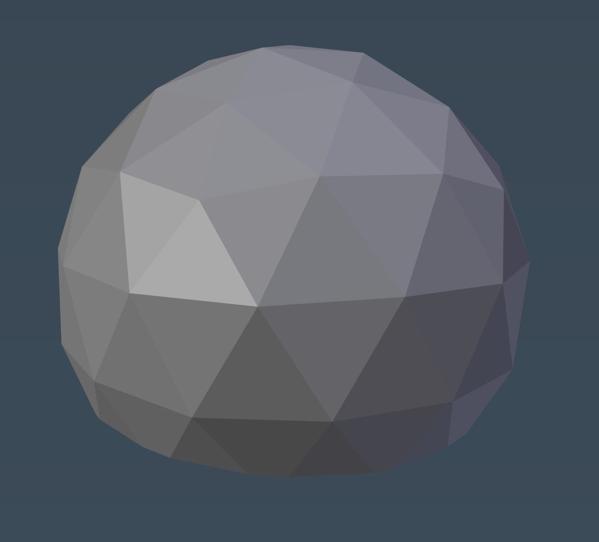
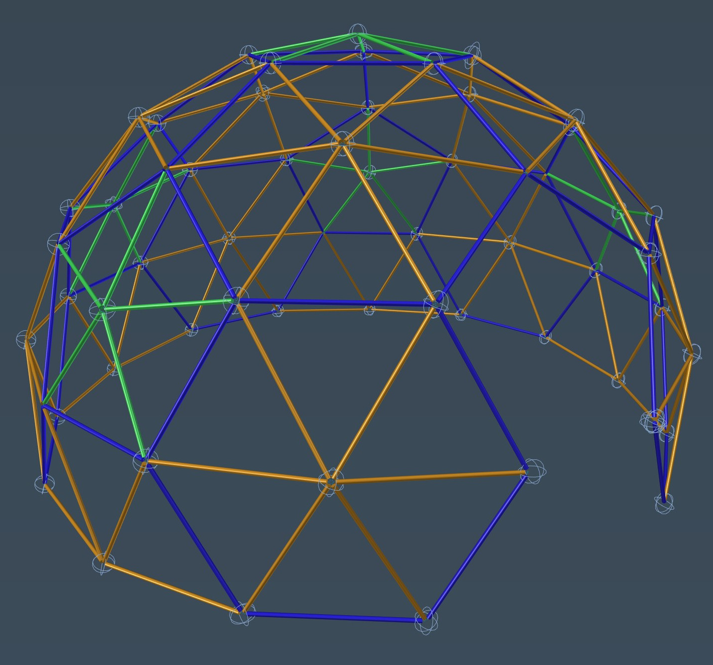
Well, how do you design a geodesic dome altogether? The simplest route is to use the geodesic plug-in for Blender, of course. One click, or actually several hours of fiddling around until the realisation dawned that there is a lot to learn about these kinds of domes, and I had a dome.

plugin-options

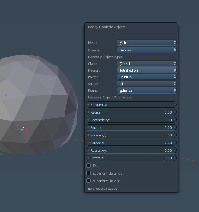
Well, sort of. What I had was a geodesic mesh, certainly; but a practical, buildable model it was not. The sheer amount of options was quite overwhelming, and then I had to scratch my head and decide whether I wanted a class 1 or class 2 icosahedron, octahedron or tetrahedron or who knows what. Obviously, I got somewhere in the end.

basic-dome

Yet there were more decisions to be made. Ideally I wanted the sukkah to fill up as much space of my garden as possible. I didn’t want the walls to be too shallow, because then much of the usable space would be sacrificed. On the other hand, if the dome was too tall, the base would be too narrow. Ah, choices, choices.

man-domes

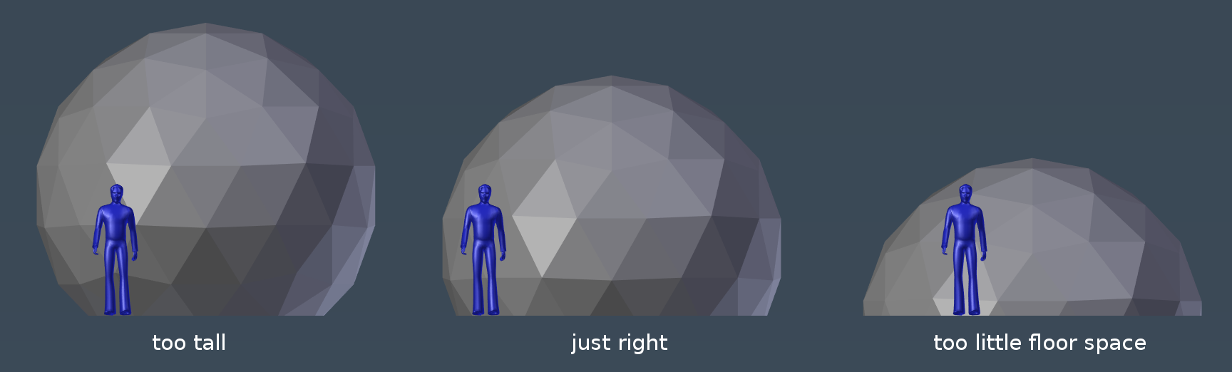
In the end I decided on a maximum diameter of 4.6m, and cut off around 1.3m off the bottom which made for a happy balance.

Of course I still had no connectors, and now way of aligning all the connectors automatically, as well as putting the pipes in place and whatnot. All of this required a fair bit of hair pulling and many hot baths.

Fortunately Blender has some really powerful tools that came handy, such as the Dupliverts tool. By parenting a mesh to the dome, Dupliverts will stick a copy of the mesh onto each face or vertex, and when using vertices will point the mesh in the direction of the vertex normal. In plain English, you get loads of free copies and everything points to the correct direction. Coolio.dupliverts

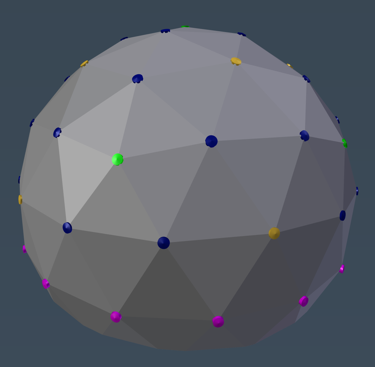
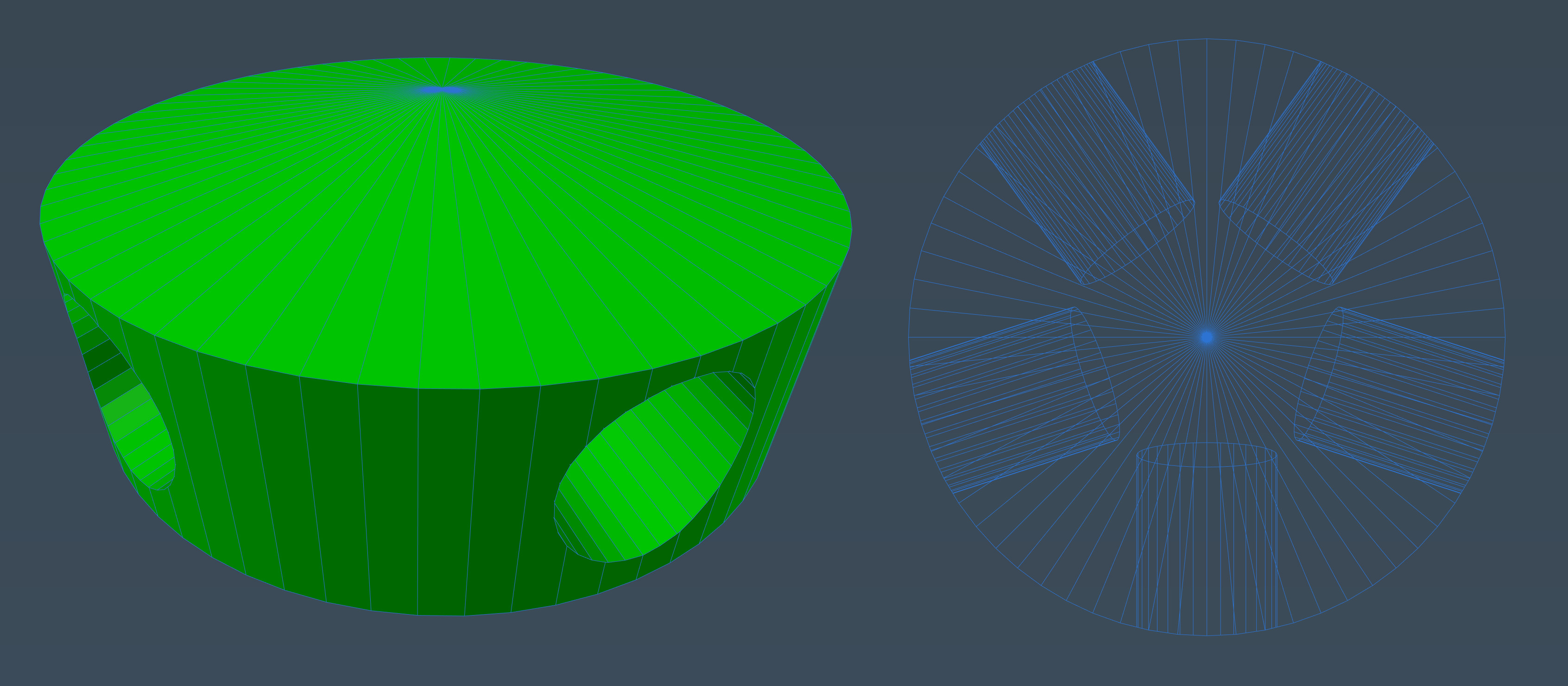
I trolled around the intarwebs to see how everybody else designed their connectors, especially the 3D printed versions, and discovered no-one who had designed an actual working dome using 3D printed parts, and the other connectors that I found were made out of bits of plastic tubing with holes drilled in and cable ties to hold it all together. Mucho too much work for my liking.

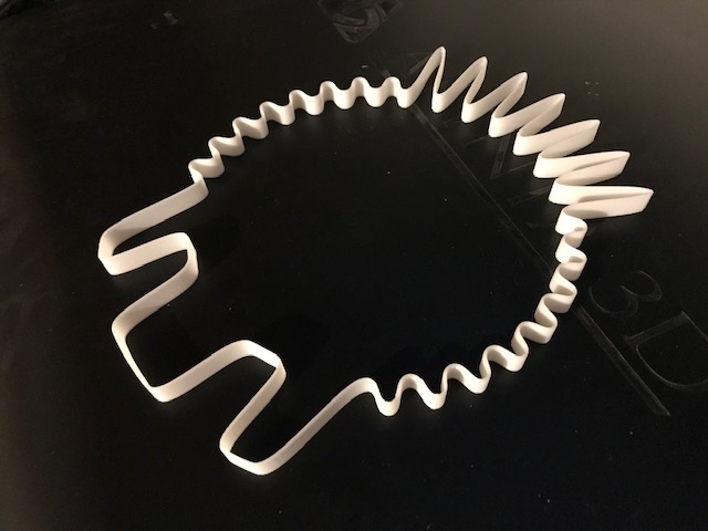
Well, after some cogitation I came up with a fairly clunky but serviceable design, which took 2 hours to print, despite using a 0.8mm nozzle and 0.3mm layer heights.

1st-design-hub

They were put into service nonetheless in order to test the very top of the dome together with the oh-so-wonderful plastic tubing.

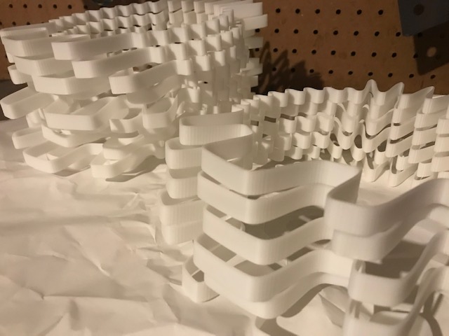
After further cogitation and the dawning of the realisation that Sukkos was fast approaching and I simply did not have the time to print dozens of clunkers, version 2 was developed. It prints in one quarter the time and uses a lot less plastic.

stars

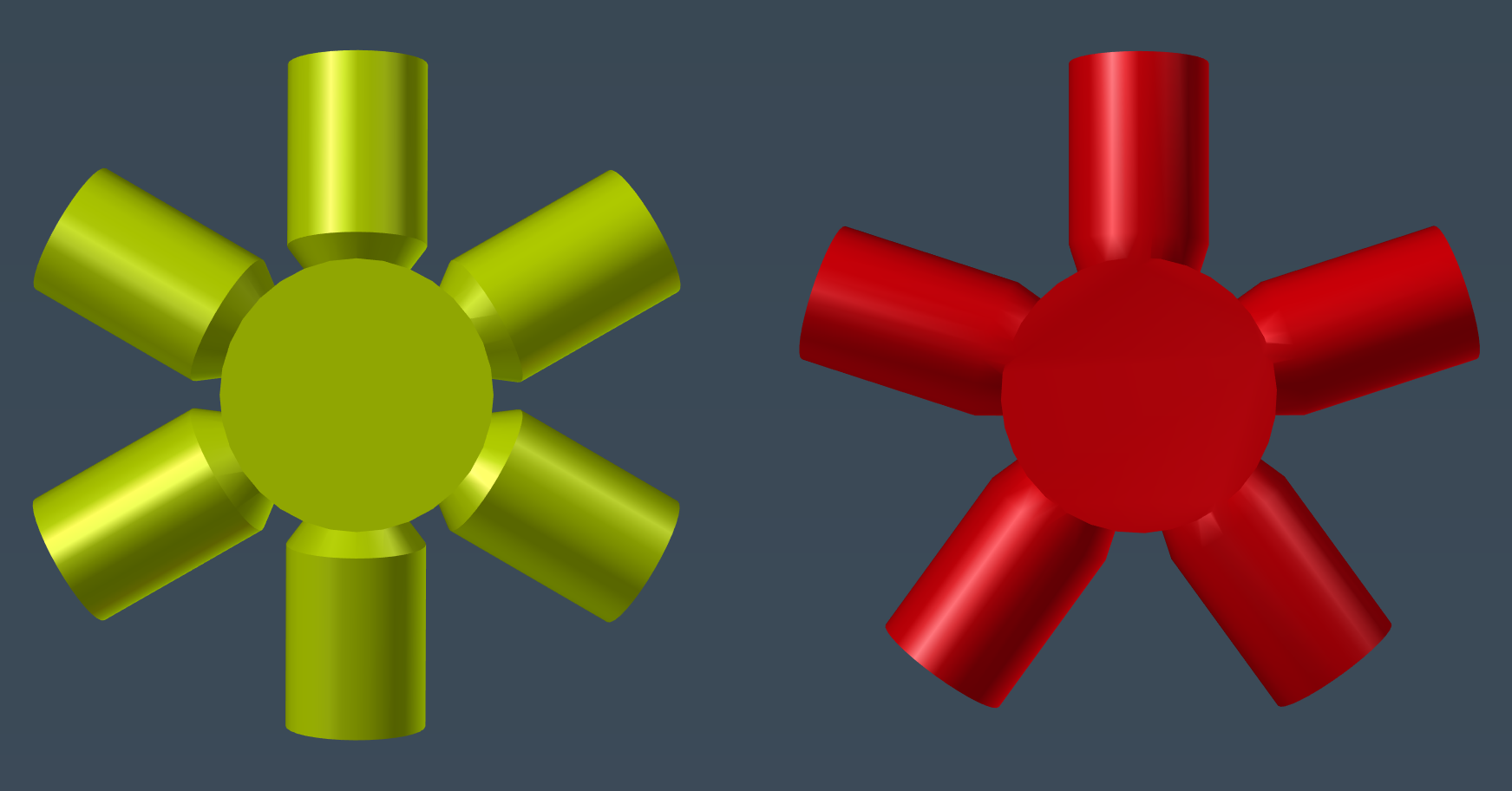
All the parts for the sukkah were printed in ABS, because they were going to be used outdoors and I didn’t want PLA melting in hot sunlight. In hindsight, this was an overly unnecessary precaution, since we rarely get sunlight in this part of the world, and when we do, heat is usually not an issue. Oh well, at least ABS is the cheapest filament I can buy, so all was not futile.

Getting the pipes in place was a bit trickier. What I resorted to in the end was using two empties, one at either end of the pipe, with the pipe parented to one, and tracking the other using a Track To constraint. Then snapping the empties to the desired vertices was simples, and some shuffling along of the pipe was in order to get it into place. Very, very tedious, not technically accurate, but quite effective.

empties

Some stats:

  • 180 pipes were cut to length from 100 x 2m lengths
  • There were a total of 62 hubs printed
  • Approximately 20 metres of cloth was used
  • 25 poles were 75.5cm long
  • 76 poles were 90cm long
  • 54 poles were 88 cm long
  • Approximately 400 screws were used
  • Something else interesting was going to go here, but I forget what
  • Yes, I only listed 155 poles’ dimensions – there were others, I did not miscount

My family took to the idea like a roasted duck to an orange sauce. Everyone was both excited and convinced I was kidding them, until she-who-must-be-obeyed greenlighted the purchase of 100 flimsy pipes at the eye-popping cost of 100 British monies. You should have seen the face of the delivery man who for the life of him could not imagine what anyone would want to do with that much garbage. It really is the cheapest stuff one can acquire without resorting to nefarious goings-on or actual miracles.

2016-10-02-13-23-27s

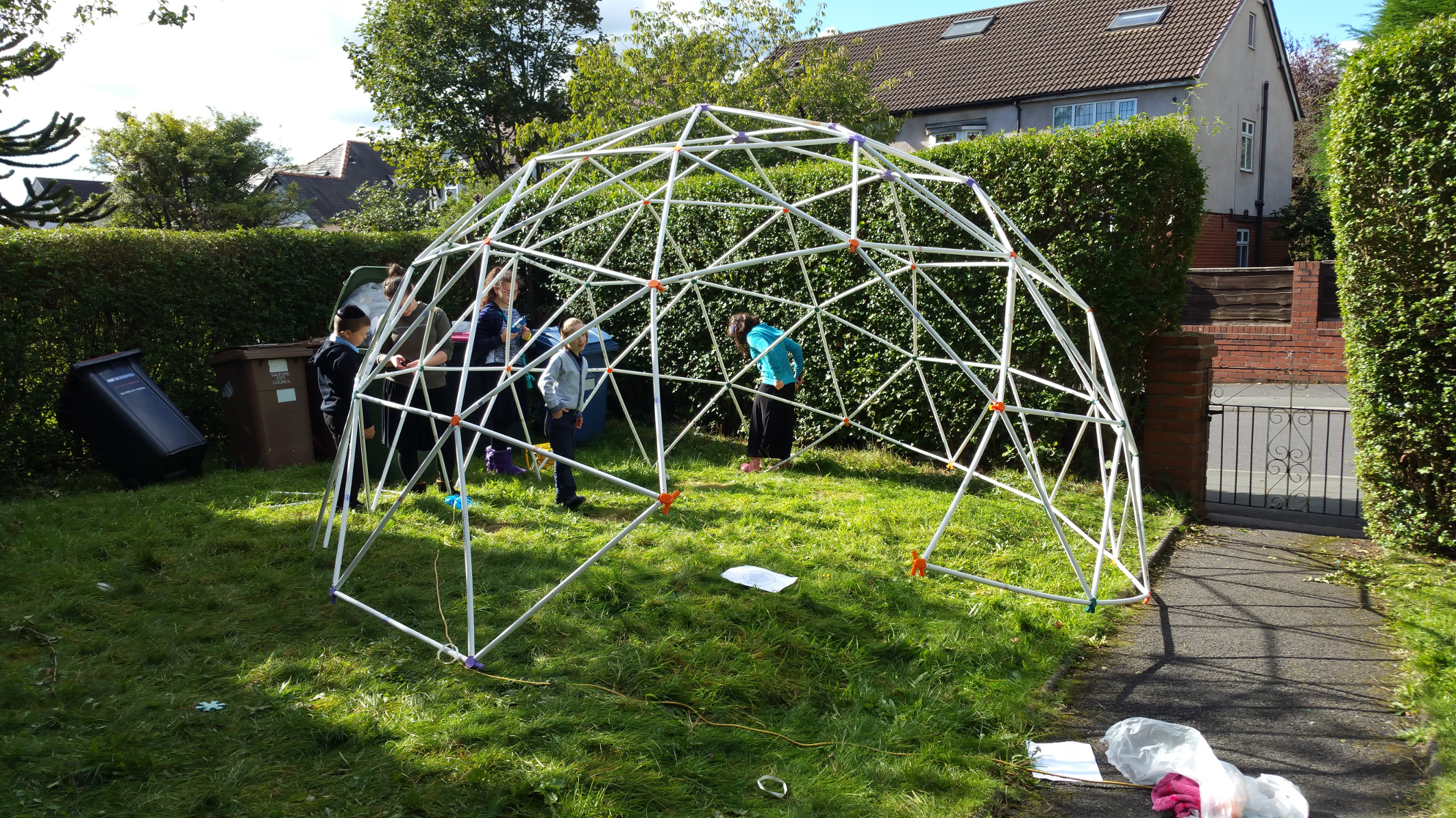
My philosophy is to avoid any actual work, and hence convinced my daughters of 12 and 14 tender years that they would be able to construct this affair with ease, and that It Would Be Quite Fun. The initial plan of simply assembling the whole thing and hoping the structure would hold itself together was quite naive, so we were forced to use small screws. This was a mixed blessing, but my dearly beloved offspring persevered, and after 20 hours of delighted labour the deed was done.

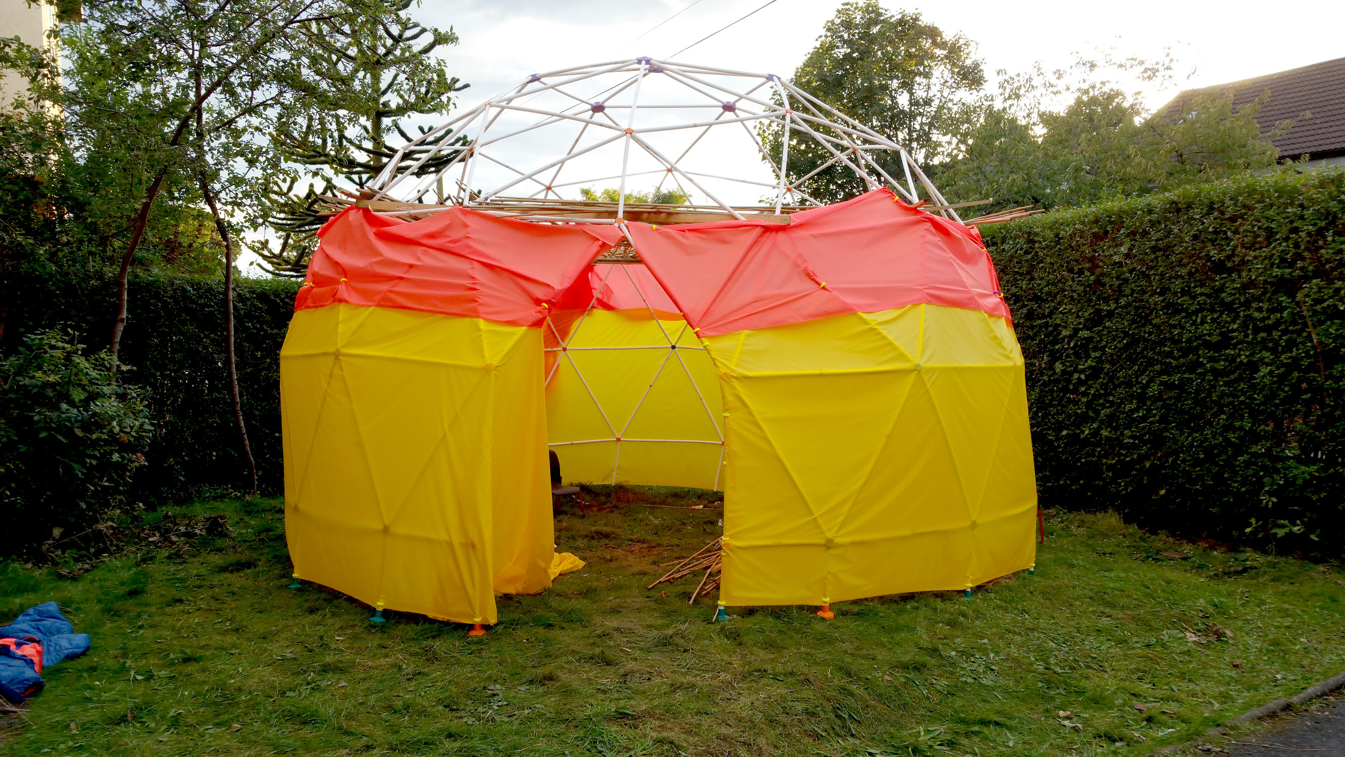
Well, at least the frame was up.

3

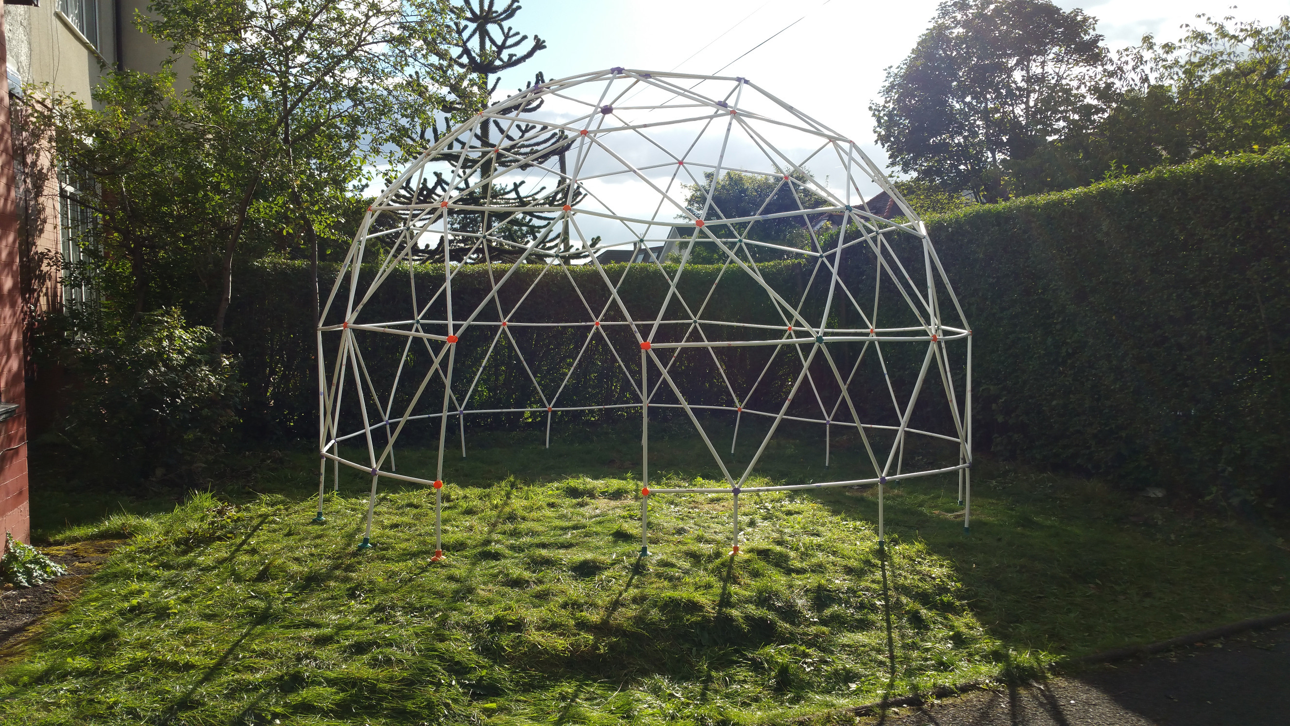
The whole affair was very much lastminute.com so not everything worked out quite as well as I hoped it would, in particular the schach (vegetation roof). Well, it still held up for the while festival, and seated 20 people in comfort, so who can complain?

The whole neighbourhood got to here about it as well, so we entertained approximately 500 visitors who wanted to eyeball the “climbing frame sukkah”.

Octoprint and the Ultimaker 2

Having finally concluded that the whole fiddling with an SD card to get my Ultimaker 2 printing was growing long in the tooth, I roped in a spare Raspberry Pi to act as a 3D print server.

Finding the info required to do this in one place is still quite tricky, so I figured I would write it all down while I still remembered.

First of all, octopi was installed on the raspberry. Of course I was too tired to realise that the image was downloaded as a zip, and I wrote the zip file to the SD card using dd several times until the light dawned, and I cursed roundly at my foolishness. One unzip later, 3.3Gb of data transferred smoothly. The raspberry pi was wired up to the printer and a handy ethernet cable and breathed into life.

Instructions listed here were slavishly followed, and then it was time to give things a whirl.

Firstly, the baudrate in the connection section has to be configured for 250000. Very important. After that there was really not much to do. I decided to install every plugin on a whim, which proved quite useful since there is no “go faster” button, and the custom control plugin allowed me to add one with little fuss (the g-code is M220, e.g. M220 S120 for 120% printing speed). As my benighted offspring might say: “Well wikkid”.

The next big change takes place in Cura, where the UltiGCode has to be switched out for RepRap(Marlin/Sprinter) in the machine settings dialog.

After that, things change a little in Cura, most importantly is the Start/End-GCode tab that appears. This will have to be modified in order to get the results you expect, such as having the head travel to the front of the table and dribble sufficient quantities of expensive filament to no end other than to prime the nozzle, and drop the bed after printing.

So, here be the code:

Err, not quite. Just a quick note, and then the code. M117 appears to do absolutely nothing at all. Nada. Nichts.

Ok, here really is the code.

Start code

;Sliced at: {day} {date} {time}
;Basic settings: Layer height: {layer_height} Walls: {wall_thickness} Fill: {fill_density}
;Print time: {print_time}
;Filament used: {filament_amount}m {filament_weight}g
;Filament cost: {filament_cost}
;M190 S{print_bed_temperature} ;Uncomment to add your own bed temperature line
;M109 S{print_temperature} ;Uncomment to add your own temperature line
G21 ;metric values
G90 ;absolute positioning
M82 ;set extruder to absolute mode
M107 ;start with the fan off
G28 X0 Y0 ;move X/Y to min endstops
G28 Z0 ;move Z to min endstops
G1 F12000 X5 Y10 ;move hotend to front left
G1 Z15.0 F{travel_speed} ;move the platform down 15mm
G92 E0 ;zero the extruded length
G1 F200 E5 ;extrude 5mm of feed stock quickly
G1 F50 E15 ;extrude 15mm of feed stock slowly
G92 E0 ;zero the extruded length again
G1 F{travel_speed}
;Put message on LCD screen - well, not really coz it don't work
M117 Printing...

End code

;End GCode
M104 S0 ;extruder heater off
M140 S0 ;heated bed heater off (if you have it)
G91 ;relative positioning
G1 E-1 F300 ;retract the filament a bit before lifting the nozzle, to release some of the pressure
G1 Z+0.5 E-5 X-20 Y-20 F{travel_speed} ;move Z up a bit and retract filament even more
G28 X0 Y0 ;move X/Y to min endstops, so the head is out of the way
G28 Z0 ;move Z to min endstops
M84 ;steppers off
G90 ;absolute positioning
;{profile_string}

That’s really that.